
Here is a quick hack to interface a temperature sensor to a BeagleBone Black unit.
I choose to use a Microship TCN75AVOA component. This SMS component is not really easy to use for prototyping but feasible. This component have a unit cost < 1€ and operate at 5V or 3.3V (as for BeagleBone). A Dip8 version exists. The communication with the CPU is numerical based on a two wire connection type I2C. It measures from -40°C to +125°C on 8b + 4b decimal with +/- 1°C precision.
Read next :

BBB temperature sensors
Here is how to look like … nice isn’t it ?!? ok … don’t comment !
So the connection is quite easy once you are able to connect some wire to the CMS component.
The circuit is the following :
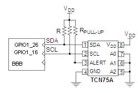
BBB temp sensor schema
GPIO1_28 (gpio60) is used for SDA (Data), GPIO1_16 (gpio48) is used for SCL (Clock).
A0, A1, A2 are used to indicate the sub address of the chip.
I used 10K Pull-up resistor and 3.3V VDD.
For implementation, we may have different way to interface an I2C component with Linux, really beautiful, integrated and so on. But … I prefer the basic way and will give you some peace of bash code to do it.
The principle is to generate the bus signals by manually changing the values on the SDA & SCL wires.
SCL use is simple, it is an output GPIO used for clock signal.
SDA use is different : it can be an input or an output and for each octet transmitted from the BBB, the sensors will send a ACK/NACK bit to be read.
Basically, each frame starts with a start message, then have the 7b I2C device address + 1 bit operation (read or write), confirmed by an ACK from this device. It can be followed by a 8b register address or a 16b read or write.
Let see an example, for details, you can check directly the component document :

I2C example
Now, lets take a look to the source code I used :
To start, some really dirty code to have a tempo < 1s:
short_sleep() {
  local i=0
  while [ $i -lt 100 ] ; do
      i=$(( $i + 1 ))
  done
}
Some constant and configuration stuff:
gpio_base=/sys/class/gpio
sda_pin=gpio60
sda_num=60
scl_pin=gpio48
scl_num=48
debug=1
#address
ad6=1 ; ad5=0 ; ad4=0 ; ad3=1 ; ad2=0 ; ad1=0 ; ad0=0
#constant
rd=1
wr=0
ack=0
nack=1
Then the gpio configuration:
init_gpio() {
   # gpio 60 is SDA
   # gpio 48 is SCL
   if [ ! -r ${gpio_base}/${sda_pin} ] ; then
       echo ${sda_num} >${gpio_base}/export
   fi
   if [ ! -r ${gpio_base}/${scl_pin} ] ; then
       echo ${scl_num} >${gpio_base}/export
   fi
   if [ -r ${gpio_base}/${scl_pin} ] ; then
       echo high > ${gpio_base}/${scl_pin}/direction
   else
       print_debug "${scl_pin} not correctly initialized"
       exit 1
   fi
   if [ ! -r ${gpio_base}/${sda_pin} ] ; then
       print_debug "${sda_pin} not correctly initialized"
       exit 1
   fi
}
set_sda_out() {
   echo out > ${gpio_base}/${sda_pin}/direction
}

set_sda_in() {
   echo in > ${gpio_base}/${sda_pin}/direction
}
Some code to read/write start / stop and bit:
send_start() {
   # set sda high, scl low
   echo high > ${gpio_base}/${sda_pin}/direction
   echo 0 > ${gpio_base}/${scl_pin}/value
   short_sleep

   # set scl high
   echo 1 > ${gpio_base}/${scl_pin}/value
   short_sleep

   # set sda low
   echo 0 > ${gpio_base}/${sda_pin}/value
   short_sleep

   # set scl low
   echo 0 > ${gpio_base}/${scl_pin}/value
   short_sleep
}
send_stop() {

  # set sda low, scl low
   echo low > ${gpio_base}/${sda_pin}/direction
   echo 0 > ${gpio_base}/${scl_pin}/value
   short_sleep

   # set scl high
   echo 1 > ${gpio_base}/${scl_pin}/value
   short_sleep

   # set sda high
   echo 1 > ${gpio_base}/${sda_pin}/value
   short_sleep

   # set sda low
   echo 0 > ${gpio_base}/${sda_pin}/value
   short_sleep

   # set scl low
   echo 0 > ${gpio_base}/${scl_pin}/value
   short_sleep
}


send_bit() {
   #set bit on sda
   echo 0 > ${gpio_base}/${scl_pin}/value
   echo $1 > ${gpio_base}/${sda_pin}/value
   short_sleep

   echo 1 > ${gpio_base}/${scl_pin}/value
   short_sleep
   echo 0 > ${gpio_base}/${scl_pin}/value
   short_sleep
}

read_bit() {
   # return bit
   echo 1 > ${gpio_base}/${scl_pin}/value
   short_sleep
   ret=`cat ${gpio_base}/${sda_pin}/value`
   echo 0 > ${gpio_base}/${scl_pin}/value
   short_sleep
   return $ret
}
Now, we can use all of this to create write address, read / write byte :
send_address() {
   set_sda_out

   send_bit $ad6
   send_bit $ad5
   send_bit $ad4
   send_bit $ad3
   send_bit $ad2
   send_bit $ad1
   send_bit $ad0
   send_bit $1

   set_sda_in
   if read_bit ; then
       print_debug Retour address : ACK
       return 0
   else
       print_debug Retour address : NACK
           return 1
   fi
}

send_byte() {
   set_sda_out

   send_bit $1
   send_bit $2
   send_bit $3
   send_bit $4
   send_bit $5
   send_bit $6
   send_bit $7
   send_bit $8
   set_sda_in
   if read_bit ; then
       print_debug Retour address : ACK
       return 0
   else
       print_debug Retour address : NACK
           return 1
   fi

}

read_byte() {
   set_sda_in
   read_bit
   echo -n $?
   read_bit
   echo -n $?
   read_bit
   echo -n $?
   read_bit
   echo -n $?
   read_bit
   echo -n $?
   read_bit
   echo -n $?
   read_bit
   echo -n $?
   read_bit
   echo -n $?

   #send ack
   set_sda_out
   send_bit $1
   echo
}
And finally we just have to build frame and get the temperature :
main() {
   init_gpio

   # send a frame to select the register 0 (temperature)
   send_start
   send_address $wr
   send_byte 0 0 0 0 0 0 0 0
   send_stop

   # now read the two byte of temperature
   send_start
   send_address $rd
   read_byte $ack     # read temperature, integer part
   read_byte $nack    # read temperature, decimal part
   send_stop
}
main $*
The result is print as a binary string… some simple transformation are needed, but this is a simple proof of concept, easy to evolve.
maybe you can use the device tree which will make your code look better.