

Raspberry PI Shiel Hat standard
When you want to design a shield for Raspberry Pi, you have to follow the HAT standard. This standards describes the form factor of the shield to ensure future compatibility. It also describes the configuration solution for the board based on a flash containing necessary information. The Hat standard link gives all the detailed specification to design a such shield. In this post I’ll describe my experience of designing such shield and you will find the basic elements I build and now sharing with you.
Design the board
The first step is to design the board following the HAT standard ; the next picture is an extract from the documentation on github, to start your design, please always refer to github here (https://github.com/raspberrypi/hats/blob/master/hat-board-mechanical.pdf) has it could be subject to change. The kicad resource I’m sharing are based on this extract
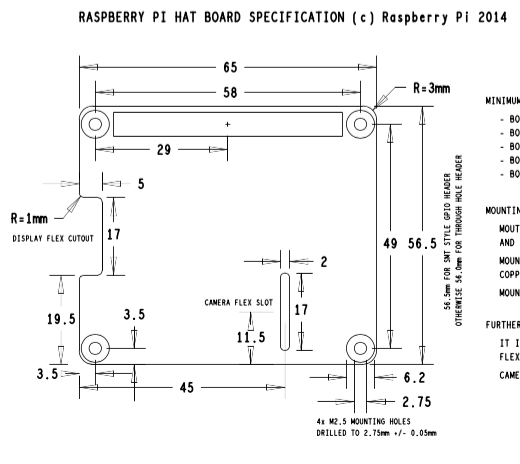
Hat shield mechanical specifications
Based on this, you can find the Kicad empty PCB corresponding to this and looking like this with the eprom already routed

kicad version of HAT design
The following github contains the full kicad project with shematics, component libs …
https://github.com/disk91/hat-design
Select the chips

hat compatible header
One of the main issue I had was to find a 2×20 PIN header corresponding to the requirement : a height between 10 and 12 mm ; one of the corresponding model is the 3M 4P01-2A02-DA that can be found here
- http://www.digikey.fr/product-search/fr?x=0&y=0&lang=fr&site=fr&KeyWords=3M10619-ND (4.65€ HT / unit)
- http://www.mouser.fr/ProductDetail/3M-Electronic-Solutions-Division/4P01-2A02-DA/?qs=yDj%2FBb4wmPEDM94jFjRvdQ%3D%3D
But, I recommend to use these other one that fits better because you have to take into account the 2mm of plastic on the male header :
Another compatible header is : PPPC202LFBN-RC (3€)
from Sullins Connector Solutions – less expensive, but ensure the size is right before ordering – my reading of the documentation is only 8.5mm high. But with the 2 mm of the header plastic on the board, it is 10.5mm. You can source here :
- http://www.digikey.com/product-search/en?x=0&y=0&lang=en&site=us&keywords=S7123-ND
Or this one from 3M: 929975-01-20 (2.6€)
- http://www.mouser.fr/Search/ProductDetail.aspx?R=929975-01-20virtualkey51750000virtualkey517-929975-01-20
Then you can use a 11mm spacer between the Pi and the shield like this one :
- http://au.mouser.com/Search/
ProductDetail.aspx?R=M1258- 2545- SSvirtualkey68520000virtualkey 761-M1258-2545-SS
If you have better sourcing, please tell me in the comment as this one is expensive !
Then you have to select a flash, I choose a CAT24C32WIG from On Semiconductor, following Hat spec recommendations, you can find here
- http://www.digikey.fr/product-detail/fr/CAT24C32WI-G/CAT24C32WI-GOS-ND/2061011 (0,6€)
- http://www.mouser.fr/ProductDetail/ON-Semiconductor/CAT24C32WI-G/?qs=sGAEpiMZZMuVhdAcoizlRUcTcLSfHcN3Sw6b4QhAlcE%3d (0,5€)
Ensure you have the last firmware
as root execute the firmware update
# rpi-update
Then reboot and check firmware version
# /opt/vc/bin/vcgencmd version
you should be version >= 27 Mar 2015 with kernel >= 3.18.10
Program the Serial Flash
The Serial flash contains the description of the shield and the configuration of the different pin. Take a look on the Hat Github to get the details on how it works. To create your flash, you can do like this:
Get the github hats tools on your raspberry Pi
# git clone https://github.com/raspberrypi/hats.git
# cd hats/eepromutils
Then you can edit the file eeprom_settings.txt file with your content ; in blue in the file, what I changed to match my card
########################################################################
# Vendor info

# 128 bit UUID. If left at zero eepmake tool will auto-generate
# RFC 4122 compliant UUID
product_uuid 00000000-0000-0000-0000-000000000000

# 16 bit product id
product_id 0x0001

# 16 bit product version
product_ver 0x0001

# ASCII vendor string (max 255 characters)
vendor "Disk91"

# ASCII product string (max 255 characters)
product "SigFox TD1204 Shield"
The next part is about GPIO configuration : in my shield, my configuration is the following one :
<Header GPIO>  |  <Header PIN> | <Board use> | <Type>
GPIO27         |       13      |    LED      | Output - Low
GPIO22         |       15      |    LED      | Output - High
GPIO18         |       12      |    LED      | Output - High
TX             |        8      |    Serial   | Output
RX             |       10      |    Serial   | Input
GPIO23         |       16      |    GPIO     | Unconnected
GPIO24         |       18      |    GPIO     | Unconnected
GPIO25         |       25      |    GPIO     | Unconnected
In the eeprom file we can configure this like
########################################################################
# GPIO pins, uncomment for GPIOs used on board
# Options for FUNCTION: INPUT, OUTPUT, ALT0-ALT5
# Options for PULL: DEFAULT, UP, DOWN, NONE
# NB GPIO0 and GPIO1 are reserved for ID EEPROM so cannot be set

# GPIO FUNCTION PULL
# ---- -------- ----
#setgpio 2 INPUT DEFAULT
#setgpio 3 INPUT DEFAULT
#setgpio 4 INPUT DEFAULT
#setgpio 5 INPUT DEFAULT
#setgpio 6 INPUT DEFAULT
#setgpio 7 INPUT DEFAULT
#setgpio 8 INPUT DEFAULT
#setgpio 9 INPUT DEFAULT
#setgpio 10 INPUT DEFAULT
#setgpio 11 INPUT DEFAULT
#setgpio 12 INPUT DEFAULT
#setgpio 13 INPUT DEFAULT
#setgpio 14 INPUT DEFAULT
#setgpio 15 INPUT DEFAULT
#setgpio 16 INPUT DEFAULT
#setgpio 17 INPUT DEFAULT
setgpio 18 OUTPUT UP
#setgpio 19 INPUT DEFAULT
#setgpio 20 INPUT DEFAULT
#setgpio 21 INPUT DEFAULT
setgpio 22 OUTPUT UP
setgpio 23 INPUT UP
setgpio 24 INPUT UP
setgpio 25 INPUT UP
#setgpio 26 INPUT DEFAULT
setgpio 27 OUTPUT DOWN
I assume Serial Port is configured another way by the system.
This configuration file made, you have to compile it with the eepmake tool.
# first step is to compile eepmake tool itself
> make eepmake
# then execute it
./eepmake eeprom_settings.txt eeprom_settings.eep

Add the white jumper to write the flash
Now, before flashing the EEPROM, you must place a jumper on the shield flash header to allow writing into the flash. Then you can flash the board.
Before being able to write the eeprom, we must activate the I2C device ; since device-tree implementation is seems to be unactivated by default.
Edit the file /boot/config.txt and add the following line : dtparam=i2c_vc=on
Then reboot.
Once done, you should be able to run
./eepflash.sh -w -f=./eeprom_settings.eep -t=24c32
Now, if you reboot and have the right firmware version, you should get en entry in the /proc/device-tree/hat directory where you will get the eeprom information in the different files.
You can remove the dtparam setting in the config.txt file
Create a device-tree file
It seems that actually HAT serial configuration is not yet ready, so to have the device correctly configure a device tree file have to be provided. To make this, you have to start by creating a dts (source file) then compile it into a dtb (binary file) and add it to the /boot/overlay directory
To get the compiler install it:
# apt-get install device-tree-compiler
See later … I’ll complete this post later when getting more time & information about this part. Come back 🙂
Can the KICAD design files be used in a windows version of KiCad?
I assume it should
hi, I have a question.
now I ‘m studying a device tree, but I found that raspberry pi use HAT ….
but I don’t know exatly what it is(HAT) and why this is needed ?
if I don’t want to use HAT , Can I use device tree directly?
if must use HAT, how to loaded from this eeprom ?
I want to see algorithm or source( ex) HAT is decompressed and changed like flatten device-tree )
wait your reply
answer please
HAT is a standard to make a RPI shield with electrical and mechanical elements. HAT is using device-tree. Read my posts about HAT, I think you will get some elements on what it is and you will find the right links to go further.
In the HAT eeprom you will load device tree so both works together.
I’ve a question about the RPI HATs… is that possible to use two HATs together? As far I understood the RPI reads the i2c EEPROM to get configuration details, but it doesn’t specify what happens if there are two HATs stacked on top of each other. My understanding is that is not supported for many reasons, including that might be a conflict of I2C addressing. Am I right?! Thanks for any input…
I assume it is not working actually. By the way, we could have different ERPOM with different addresses. But it is actually not documented in the standard as much as I know.
Are you sure the KiCad schematics are correct? Should not the EEPROM be wired to GPIO pins 0 and 1 (3 and 5 on the header?)?! As per https://github.com/raspberrypi/hats/blob/master/designguide.md !?
Thanks,
Marcel
EEPROM is attached to the second I2C
My very bad! You are absolutely right – the documentation on the raspberrypi wiki is a bit missleading
Pingback: Embedded product with Raspberry Pi Compute Module - disk91.com - technology blogdisk91.com – technology blog